Skip to content
Electronic Circuits

DIY Hobby projects, diagram, schematic

Electronic Circuits

DIY Hobby projects, diagram, schematic

SCR TESTER

electronicecircuits, February 6, 2010August 17, 2023

SCR Silicon controlled rectifier TESTER

SCR TESTER CIRCUIT

The Device under test cathode, anode and gate are connected to the unit’s CATHODE, ANODE and GATE terminals, respectively. You can easily check SCR using this SCR tester circuit.
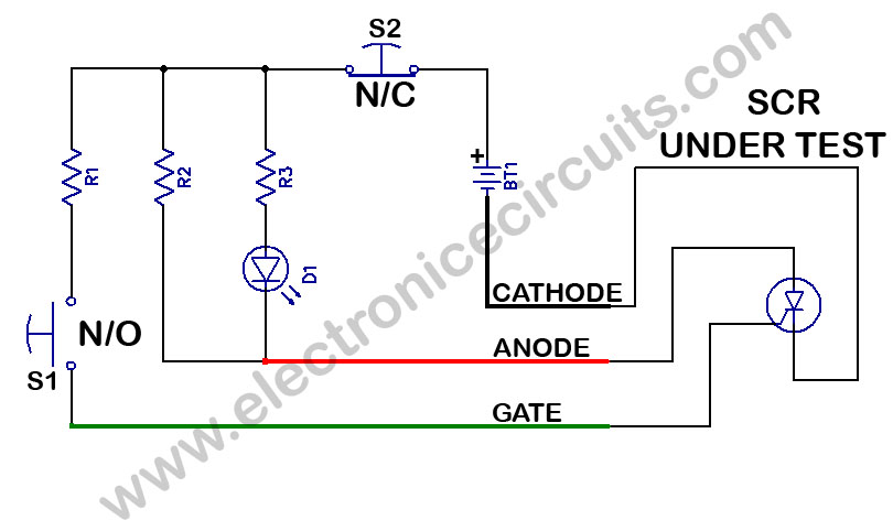
scr or Silicon controlled rectifier tester circuit diagram
PARTS LIST
R1100Ω
R2100Ω
R3390Ω
D1LED
S1push button normally open switch
S2push button normally closed switch
BT19V BATTERY

Pressing switch S1 feeds a gate current to the DUT (Device Under Test), which triggers it on. Resistor R1 limits the gate current to the appropriate level. Resistor R3 limits the current through the LED to about 20 mA which, with the  current through R2, results in a latching current of about 110 mA. The LED is used to monitor the latching current. IF the DUT is good, once the gate is triggered with S1, the LED will remain light, indicating that the device is conducting. To end the test, turn off the device by interrupting the latching current flow using switch S2. The LED should turn off and remain off. The preceding procedure will work SCRs and Triacs. To check LED and other diodes, connect the anode and cathode leads to the anode and cathode of the diode; LED should light. When the leads are reversed, the LED1 should remain off.

Please send your ideas, which are very important for our success…

Electronic Circuits Tester Circuits

Post navigation

Previous post
Next post

Comments (9)

  1. school grants says:
    April 11, 2010 at 5:52 am

    What a great resource!

    Reply
  2. Carry says:
    October 14, 2010 at 5:33 am

    Thanks so much for writing all of the excellent info! I am looking forward to seeintg more posts.

    Reply
  3. david deangelo says:
    October 26, 2010 at 4:24 am

    Very educating write up, bookmarked the blog for interest to see more!

    Reply
  4. Josefa Meach says:
    October 29, 2010 at 11:48 am

    The nice post helped me very much! Saved your website, extremely great categories everywhere that I read here! I really appreciate the info, thanks.

    Reply
  5. Fatimah Majocka says:
    November 4, 2010 at 11:08 pm

    Helpful blog, bookmarked your blog with interest to read more information!

    Reply
  6. Agustin says:
    April 7, 2011 at 3:48 pm

    This has been good quality information and facts you presented relating to this subject. I don’t agree with every thing, nevertheless, you absolutely produced some good points.

    Reply
  7. voli low cost scegli questo says:
    July 12, 2011 at 8:40 am

    I’m italian geek girl! Tks for u entry…

    Reply
  8. ya.vasch1950 says:
    May 9, 2013 at 9:58 pm

    Очень хорошая и практическая схема. СПАСИБО!.
    Іван.

    Reply
  9. enhassan says:
    November 6, 2014 at 9:34 am

    very good

    Reply

Leave a Reply Cancel reply

Your email address will not be published. Required fields are marked *

  • Diagrams
  • Privacy Policy
  • Software
  • Contact

Recent Posts

  • LM317 CONSTANT CURRENT CALCULATOR
  • 5V buck converter – LM2576 simple DIY project
  • ICL7107 PANEL METER
  • Precision 1Hz clock generator circuit
  • Toggle to Momentary Switch Using 555 Monostable

Categories

  • Circuit Tutorials
  • Electronic Circuits
  • Electronic Software

AC Projects Alarm Circuits Amplifier Circuits Amplifiers Antenna Circuits Battery Charger Calculator software Circuit Designer Control Circuits Converter circuits Crossover Circuits Data Sheets Digital Circuits Electronic Switch Flasher Circuits Game Circuits IC Programmer IC Programming Indicator Circuits LED Circuits Light Circuits Logic Circuits Measuring Circuits Meter Circuits Microchip Motor Circuits Music Circuits Oscillator Circuits PCB Designer PIC Power Amplifier Power Guard Power Supply PreAmplifier Circuits Radio Circuits Regulator Circuits Regulator Diagrams Regulator Schematics RF Schematics Sensor Circuits Tester Circuits Timer Circuits Transmitter Circuits Tutorials Vacuum Tube

©2025 Electronic Circuits | WordPress Theme by SuperbThemes