
Sensitive RF Voltmeter Probe Circuit
This Circuit measures RF voltages beyond 200MHz and up to about 5V.

| PARTS LIST | |
| R1 | 4.7MΩ |
| R2 | 1MΩ |
| R3 | 1MΩ |
| R4 | 100kΩ |
| R5 | 330Ω |
| R6 | 10kΩ |
| R7 | 10kΩ |
| VR1 | 2kΩ |
| VR2 | 2kΩ |
| C1 | 0.001µF (Disc Ceramic) |
| C2 | 0.001µF(Disc Ceramic) |
| C3 | 0.01µF |
| D1 | 1N914 |
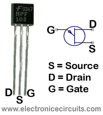
| Q1 | 2N3819, 2N5459, MPF102 |
| M1 | 100µA |
| S1 | Switch |
| BT1 | 9V Battery |
The Diode should be mounted in a remote probe, close to the probe tip. Sensitivity is excellent and voltage less than 1V peak can be easily measured. The unit can be calibrated by connecting the input to a known level of RF voltage, such as a calibrated signal generator, and setting the calibrate control.
VR1 =For Calibrate
VR2 = For Zero set
Please send your ideas, which are very important for our success…
nice post. thanks.
Great information! I’ve been looking for something like this for a while now. Thanks!
Great, I never knew this, thanks.
found your site on del.icio.us today and really liked it.. i bookmarked it and will be back to check it out some more later
Wow this is a great resource.. I’m enjoying it.. good article
This is such a great resource that you are providing and you give it away for free. I enjoy seeing websites that understand the value of providing a prime resource for free. I truly loved reading your post. Thanks!
I’ve recently started a blog, the information you provide on this site has helped me tremendously. Thank you for all of your time & work.
Genial dispatch and this fill someone in on helped me alot in my college assignement. Thanks you as your information.
I just wanted to comment and say that I really enjoyed reading your blog post here. It was very informative and I also digg the way you write! Keep it up and I’ll be back to read more in the future
a good idia