Variable Zener Diode – SUPER ZENER
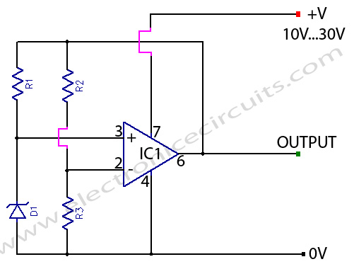
This variable zener circuit is intended primarily to produce a stable reference voltage in battery operated equipment designed for minimum current consumption. Despite the fact that only 1mA flows through the zener the output voltage showed a fluctuation of less than 1mV for supply voltage variations of 10 to 30 volts.

| PARTS LIST | |
| R1 | 2.2kΩ |
| R2 | 100kΩ |
| R3 | 220kΩ |
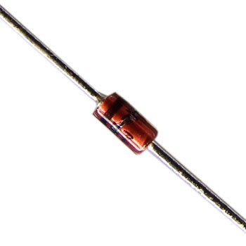
| D1 | 5.6V 400mW zener |
| IC1 | 741 op amp |
The reference voltage from the zener diode apply to the non-inverting input of a 741 op-amp and the output voltage of the zener voltage multiply by using the op-amp gain.
Vo=Vz×(R2+R3)/R3
Vo=5.6V×(100KΩ+220KΩ)/220KΩ
Vo=5.6V×1.45=8.14V
Vo=OUTPUT VOLTAGE
Vz=ZENER VOLTAGE
This approach has two advantages. Firstly, a low temperature coefficient zener (5.6V) can use to provide any desired reference voltage simply by altering the op-amp gain. Secondly, since no since no significant current is ‘robbed’ from the zener by the op-amp input, the need only be fed by a small current. So that the resistance the of zener does not affect the output voltage the zener current must be fairly constant. This achieve by feeding the zener via R1 from the output of the op-amp. The zener current is,
1mA=V0-Vz/R1
So R1 select to give a zener current of about 1mA. The reference voltage obtained from the op-amp output can supply currents of up to 15mA. One point to note when using this circuit is that the supply voltage must be at least 2V greater than the output voltage of the circuit.
Please send your ideas, those are very important for our success…
Terrific work! This is the type of information that should be shared around the web. Shame on the search engines for not positioning this post higher!
Great information! I’ve been looking for something like this for a while now. Thanks!
Keep posting stuff like this i really like it
Keep posting stuff like this i really like it
it’s nice explanation thank u 🙂
I to thank you for this good post .I definitely liked every little bit of it. I have you bookmarked your web site to look at the latest stuff you post.
You are the man ! Nice article Good luck dude . see you again tomorrow