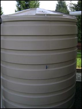
Water Tank Level Indicator Circuit Diagram
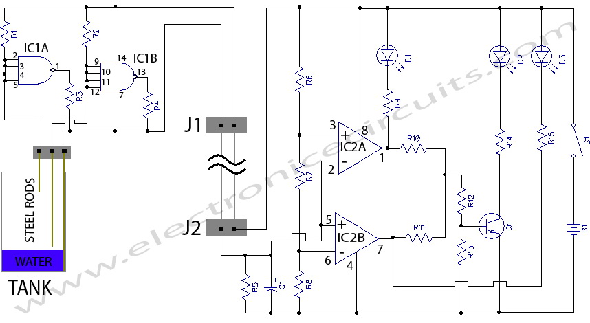
Simple water level indicator circuit, two-wire, remote monitoring unit, Three-LED level display, 9V battery powered Circuit diagram:
| PARTS LIST | |
| R1 | 15KΩ 1/4W Resistor |
| R2 | 15KΩ 1/4W Resistor |
| R3 | 1KΩ 1/4W Resistor |
| R4 | 1KΩ 1/4W Resistor |
| R5 | 100Ω 1/4W Resistor |
| R6 | 47KΩ 1/4W Resistor |
| R7 | 3.3KΩ 1/4W Resistor |
| R8 | 3.3KΩ 1/4W Resistor |
| R9 | 2.7KΩ 1/4W Resistor |
| R10 | 15KΩ 1/4W Resistor |
| R11 | 15KΩ 1/4W Resistor |
| R12 | 15KΩ 1/4W Resistor |
| R13 | 3.3KΩ 1/4W Resistor |
| R14 | 2.7KΩ 1/4W Resistor |
| R15 | 2.7KΩ 1/4W Resistor |
| C1 | 470nF 63V Polyester or Ceramic Capacitor |
| D1 | Green LED |
| D2 | Yellow LED |
| D3 | Red LED |
| Q1 | BC547 45V 100mA NPN Transistor |
| IC1 | 4012 Dual 4 input NAND gate IC |
| IC2 | LM393 Dual Comparator IC |
| J1,J2 | Two ways output sockets |
| B1 | 9V Battery |
| S1 | Switch |
| Two steel rods of appropriate length | |
Its purpose was to remotely monitor the water-level in a metal tank located in the attic by means of a very simple control unit placed in the kitchen, some floors below.
Mains requirements were:
* No separate supply for the remote circuit
* Main and remote units connected by a thin two-wire cable
* Simple LED display for the main unit
* Battery operation to avoid problems related to mains supply and water proximity
* As the circuit was battery operated a low current consumption was obviously welcomed
The very small remote unit is placed near the tank and measures the water level in three ranges by means of two steel rods. Each range will cover one third of the tank capacity:
* Almost empty – signaled by means of a red LED (D3) in the control unit display
* About half-level – signaled by means of a yellow LED (D2) in the control unit display
* Almost full – signaled by means of a green LED (D1) in the control unit display
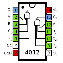 | 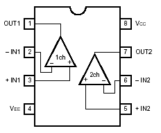 | 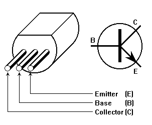 |
| 4012 NAND gate IC | LM393 Comparator IC | BC547 NPN Transistor |
Circuit operation:
When the water-level is below the steel rods, no contact is occurring from the metal can and the rods, which are supported by a small insulated (wooden) board. The small circuit built around IC1 draws no current and therefore no voltage drop is generated across R5. IC2A, IC2B and Q1 are wired as a window comparator and, as there is zero voltage at input pins #2 and #5, D3 will illuminate.
When the water comes in contact with the first rod, pin #13 of IC1 will go high, as its input pins #9 to #12 were shorted to negative by means of the water contact. Therefore, R4 will be connected across the full supply voltage and the remote circuit will draw a current of about 9mA. This current will cause a voltage drop of about 0.9V across R5 and the window comparator will detect this voltage and will change its state, switching off D3 and illuminating D2.
When the water will reach the second rod, also pin #1 of IC1 will go high for the same reason explained above. Now either R3 and R4 will be connected across the full supply voltage and the total current drawing of the remote circuit will be about 18mA. The voltage drop across R5 will be now about 1.8V and the window comparator will switch off D2 and will drive D1.
The battery will last very long because the circuit will be mostly in the off state. Current is needed only for a few seconds when P1 is pushed to check the water-level and one of the LEDs illuminates.
Notes:
* The two steel rods must be supported by a small insulated (wooden) board
* IC1 and R1-R4 are mounted on a small board placed near or on the steel rods support
* The two-wire cable connecting the remote circuit board to the main control board, i.e. J1 to J2, can be of any size and type (preferably thin for obvious reasons). It can be very long, if necessary.
* The circuit can be used also with non-metal tanks, provided a third steel rod having the height of the tank will be added and connected to pin #7 of IC1, R3, R4 and J1.
* The 4012 chip was chosen because it contains two gates and was at hand, but you can use two of the gates contained into 4001, 4011, 4093, 4049, 4069 etc. chips, provided all inputs of each gate are tied together and all inputs of unused gates are connected to the positive rail, leaving output pins open.
Please send your ideas, which are very important for our success…
I want know how to calcurate the values of the components used in circiut diagram of water level indicator using lm393 comparator.
circuit analysis of the above circuit diagram
hiiiiiiiiiiiiiiiiiii
why the simulation of this circuit cannot run?
good
Great job and everything – but the Velleman water detector kit MK108 is $6.99 at Frys and uses two resistors and a BC517 transistor. Get three of those. Or make them yourself from the available pdf.
very nice circuit.i like it verymuch
C1 470nF 63V Polyester / Ceramic Capacitor are electrolytic capacitor. Please inform me.
What value of 470nF ? Can I read this capacitor 470µF ?
Reply Please!
this circuit use power amplifier or not? and please explain to me what the different each resistor that use in this circuit.