Zener Diode Tester Circuit
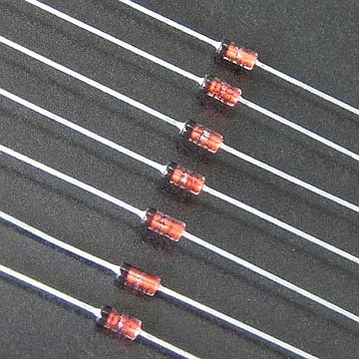
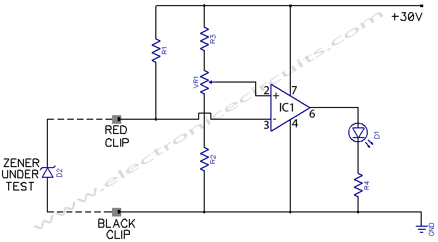
This tester helps to check the voltages of zener diodes. It is very inexpensive and handy to find the voltages of small glass zeners, whose markings get rubbed-off very easily. The 741 op-amp has been used in differential mode.

| PARTS LIST | |
| R1 | 4.7 KΩ |
| R2 | 2.2 KΩ |
| R3 | 2.2 KΩ |
| R4 | 1 KΩ |
| VR1 | 47 KΩ LIN |
| D1 | RED LED |
| IC1 | LM741 |
The 47k linear potentiometer’s dial is calibrated in terms of voltages between 0 and 27V, either by using various known zeners in the range, or by applying a known voltage at pin 3 of IC 741. The position of the potentiometer where the LED gets turned off, gives the breakdown voltage of zener.
The power supply voltage can be between 9V and 30V. But zener to be tested, and should not be changed once the dial is calibrated.
You can also check the polarity of zener. The cathode side should be connected to the red clip.(i.e. pin 3 of IC 741) If you connect the zener the other way round, then it will just behave as a diode, and the LED will remain off at all positions of the potentiometer.
In case of a zener that is shorted from inside, the LED will remain off with zener connected either way ti the clips. In case of a zener that is open-circuit from inside, the LED keeps glowing at all positions, with zener connected either way to the clips.
You may even differentiate between a diode and a zener by their behaviour on this versatile tester.
Please send your ideas, which are very important for our success…
I found your blog on google and read a few of your other posts. I just added you to my Google News Reader. Keep up the fantastic work Look forward to reading more from you in the future.
i want the oprration of zener tester circuit using ic 741? please”
I am Glad i found this website.Added http://www.electronicecircuits.com to my bookmark!
I enjoy visiting daily to see your writings. I have your page bookmarked on my daily read list!
Good blog. Going to need some time to think about this post.
very gud!!