
Power Amplifier Speaker Protection Circuit Schematic
While switching a power amplifier on, a loud thump sound is heard to sudden heavy discharge current through the speaker at the time of power on. This current may damage the speaker, especially in case of direct coupled amplifier. so you can protect that from this speaker protection circuit.

| PARTS LIST | |
| R1 | 5KΩ Preset |
| C1 | 1000µF 25V |
| C2 | 0.1µF (104) |
| D1 | IN4001 |
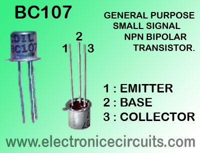
| Q1 | BC107 |
| RL1 | 9V 500Ω Relay |
| LS1 | Speaker |
The circuit given here protects speakers from the current surge. When the amplifier is off, relay switch is also off. When the amplifier is switch on, R1 and Ci provide delay of a few seconds to switch the transistor on which energizes the relay.
Delay time is proportional to value of R1.
 |  |
Please send your ideas, which are very important for our success…
Nice circuit. I would love it if it could use a 12v Cube relay instead of the 9v relay
Hmm hey, you better at least use 555 timer for this instead of capacitor.
please send me a 50w power amplifier design driven by a pre amplifier
Capacitor use is just fine do not listen to Pasanlaksiris advice!
I use C945 transistor for this schematic and it works well….thanks for the diagram sir
I am an idiot so I would rather not risk my speakers by making one myself so I am wondering where I can buy factory made units on line?!
ineed more
very nice jobs
plz i want a full picture i want to put all the components above on the board plz
This is interesting and useful circuit. Would try to build this by myself. Thanks