2N3055 power supply – DC regulated – Using LM741 Op Amp IC And 2N3055 Power Transistor
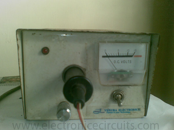
The voltage regulated power supply provides an adjustable voltage output at a load current up to 1A. The supply has a built-in overload protection. Especially below 2N3055 power supply circuit can regulate from zero voltage.

| PARTS LIST | |
| R1 | 6.8kΩ |
| R2 | 1kΩ |
| R3 | 10kΩ Potentiometer |
| R4 | 22kΩ |
| R5 | 10kΩ |
| R6 | 0.6Ω 1W |
| R7 | 330Ω |
| R8 | 2.2kΩ 1W |
| C1 | 2200µF 50v |
| C2 | 100µF 50v |
| C3 | 22µF 16v |
| C4 | o.1µF 50V |
| D1 | 3 Amp Diode |
| D2 | 3 Amp Diode |
| D3 | 1 Amp Diode |
| D4 | 6.8V 500mA Zener Diode |
| D5 | 6.8V 500mA Zener Diode |
| T1 | 2N1481 or D313 or 2SC1061 |
| T2 | 2N3055 |
| T3 | BC107 |
| IC1 | LM741 |
| TR1 | SEC 15V, 2AMP |
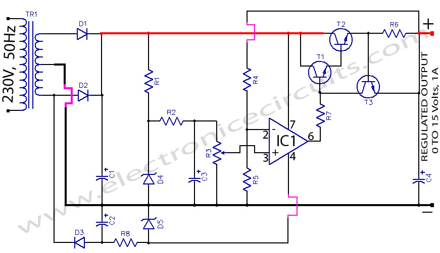
Rectifier diodes D1 and D2 along with capacitor C1 provide the main unregulated supply. D3, C2, R8 and zener diode provide a negative voltage supply for the 741. The non-inverting input terminal of 741 is given a stable voltage by R3 which is the control to set the output. A fraction of the regulated output is fed back via R4 and R5 to the inverting input terminal. The operational amplifier adjusts its output voltage so as to keep the voltage at the input terminals equal. Thus the output gets regulated. The output of 741 is amplified by a compound emitter follower T1 and T2.
All the current flows through R6. If the load current exceeds 1A, the voltage drop across R6 exceeds 0.6 volts and T3 starts conducting. This bypasses the supply to T1 and T2 and the regulating action stops. The output voltage therefore starts falling when the load current exceeds 1A. Any of the output terminals can be grounded to get a positive or a negative voltage with respect to the ground.
Also you can try this simple 2n3055 power supply circuit without using any IC.
Variable 2N3055 Power Supply 0-24V
Please send your ideas, those are very important for our success…
R1,R2,R4,R5,R7 what wattage do we use? 1W,1/2W or 1/4W. Sorry for my noobness..i just want to make this Power Supply for my Electronics project.
and btw, what fuse do we use for this?
Replay ASAP.
R1, R4, R5, R7 = 1/4W
R2 = 1/2W
you can use 500mA fuse series with TR1 230v side.
Hi please add 100 ohms 1/4w resistance in the base circuit of current limitting trasistor T3, to protect it during an out put dead short, to limit the Ibe to safe limit. without which the be junction of the transistor will blow, otherwise a nice circuit keep it up.
Amiable post and this fill someone in on helped me alot in my college assignement. Thank you for your information.
excellent information.
helpful post.
Appreciate this article, It was an incredible read that was very helpful.
for 5A use 2 2n3055?
but 5A can I use two 2n3055?
For 5A output pwer you can use BD249
Hi… really love this design doing something similar, except I need a regulated voltage of 0 – 5V and 200mA current, what resistances do I change to make that happen?
Looking for power regulator for controlling up to 20 amps at 27 volts DC using 2n3055 To be used for charging AGM and Gel cells
I build a power supply 0-150v ,0.5A
I chose T1 PNP
How do you think I’m wrong???