
4033 7 Segment Common Anode Display Event Counter Circuit
This seven segment counter circuit can count 0 to 9 with reset and display test switches.

Fig.1.
| PARTS LIST | |
| R1 – R7 | 1kΩ |
| R8 | 10kΩ |
| R9 | 10kΩ |
| R10 -R16 | 680Ω |
| R17 | 10kΩ |
| C1 | 0.1µF (104) |
| Q1 – Q7 | C828 |
| IC1 | 4033 |
| S1 – S3 | Push to ON Switch |
| Display 1 | Common Anode 7 Segment Display |
- S1 = COUNT
- S2 = RESET
- S3 = LAMP TEST
 This synchronous decade, or divide-by-10, counter provides internal decoding to drive a 7-segment display. It does not have internal count storage, nor does it provide enough output current to directly drive high-current display types. A divide-by-10 square-wave output is also available. VDD = +3 TO +15V | 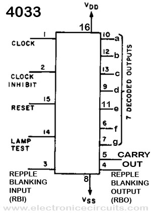 |
| 4033 IC | 4033 PIN Configuration |
| In normal operation, reset and clock enable are held at ground and the ripple blanking input is connected to ground or a more-significant count stage. The counter advances one count on each ground-to-positive (positive edge) transition of the clock input.
There are two types of outputs. At the ÷10 output, a square wave that is high for count 0 through 4 and low for counts 5 through 9 results. At the a through g outputs, a high stage is produced if a display segment is to be lit. Segments b and c are used for the “1” output. Note that the “6” output includes segment a and the “9” output includes segment d. The counter is reset to zero by bringing the RST terminal high. This results in an a-b-c-d-e-f low, along with a high on the ÷ 10 output. The RST input must be returned to ground when counting is to continue. A high on the Test input puts all outputs high for lamp or display test. To automatically extinguish all right -hand zeros, ground the RB IN terminal of the most-significant stage and connect its RB OUT to the RB IN of the next most-significant stage, and so on down the line. This zero blanking is defeated by making all RB IN terminals positive. The clock must be noiseless and have only one ground-to-positive transition per desired count. Rise and fall times should be 5 microseconds or faster. Maximum clock frequency is 5 megahertz at 10 volts and 2.5 megahertz at 5 volts. Total package current at a 1 megahertz clock rate with unloaded outputs is 0.4 mA at 5 volts and 0.8 mA at 10 volts. | |
You can increase counting number by adding below circuits.

Fig.2.
You can add any number of fig.2. circuit for increase counting number.
You must connect;
- All Y points and all Z points ( Fig.1. Y to Fig.2. Y and Fig.1. Z to Fig.2. Z)
- Fig.1. X to Fig.2. A
When you add 3rd display, second display circuit X point connect to third display circuit (like fig.2. circuit) A point.
 |  |
Please send your ideas, which are very important for our success…
i want a circuit with 2 display 7 segment that count, one display count 0 to 4 and another count 0 to 7
yes it you can make by simply reset the counter after 4 ,when disply 5 a,c,d,f,g these segment come active high that you take as a in put , using AND gate do AND operation , give the out put of the AND to the reset pin , you will get your circuit.
i want to interface two 7segment display with 1 remaining 0 uptil other becomes 9 after that they should disply 10,11,12 and so on…..and do reply on my email plss…
i want to use 5 displays….is it possible to make the counter count in increments of 5
i wish to design digital using 555 and cd 4033 counter and 7 segment dipay . if you have any circute please forward to me
I have taken some generic deli counter boards that use your design and I am using them to drive an external relay set so I can drive high powered LEDs to be used at swim meets.
I have a real need to rest this, Would it be possible to use to reset this by pulling 15 away from the ground while at the same time connecting it high. I have a remote control relay that can do this. But i want to make sure it makes sense. In the boards I have they don’t use any 10K resistors. Thanks
i want to use 3 displays…is it possible to make ?? send me circuit diagram
Do you know how to make the counting start from 1 instead of 0 ? I am trying to make a simple electronic dice that counts from 1 to 6. Thank you so much
WELL I NEED A CIRCUIT OF CD 4033 TO HOLD A SPECIFIC DIGIT WHEN SWITCHED ON OR OFF
A seven-segment display is wired as common-ANODE and connected to PORT B. RB0 through RB6 are connected to segments a through g. The command PORTB = 0xB0 is reached in the program. What will display?