Accurate 50Hz Oscillator Circuit Using 555 And 7490
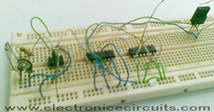
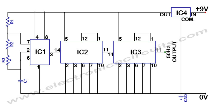
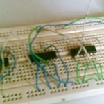
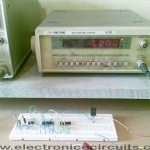
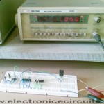
This circuit is a getting a 50Hz pulse. It comprises a 555 timer and two 7490 divide-by-ten counter chips 7490. Below 50hz oscillator circuit can give good accuracy.
| PARTS LIST | |
| R1 | 2.2kΩ |
| R2 | 142kΩ (120kΩ + 22kΩ) |
| R3 | 5kΩ PRESET |
| C1 | 0.001µF (102) |
| IC1 | NE555 |
| IC2 | 7490 (SN74LS90N) |
| IC3 | 7490 (SN74LS90N) |
| IC4 | 7805 Regulator |
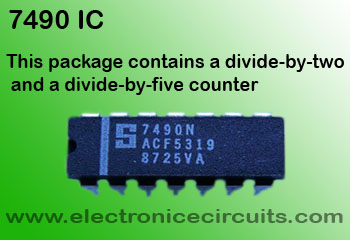
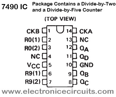
The 555 generates a frequency of almost 5KHz which can be adjusted by VR1. This pulse fed to one divide-by-ten counter IC2 (7490) which gives an output of 500Hz (500KHz/10=500Hz). This frequency of 500Hz is again fed to the next counter IC3 to get 50Hz pulse (5ooHz/10=50Hz).
 |  |
To get accurate 50Hz pulse, the 5k preset has to be set.
The circuit works on a regulated supply of 5V.
If you reducing R2 (like 120kΩ), this circuit uses as 60Hz oscillator.
Please send your ideas, which are very important for our success…
Great site. A lot of useful information here. I’m sending it to some friends!
Wow this is a great resource.. I’m enjoying it.. good article
found your site on del.icio.us today and really liked it.. i bookmarked it and will be back to check it out some more later
Writing comes more easily if you have something to say.
Amiable dispatch and this fill someone in on helped me alot in my college assignement. Thanks you as your information.
Very nice site.
bbbb
Happy new year!
Thank you good idea can help me to make 50Hz sine wave,and can you help me to give me schematic diagram frequency counter (4 digit only) ,please send to my email .Thank