
12V DC Light Dimmer Circuit Using 555 Timer IC
This is a 12 volt at 2 amp Lamp dimmer that can be used to dim a standard 25 watt bulb by controlling the duty cycle of a astable 555 timer oscillator.

| PARTS LIST | |
| R1 | 1KΩ |
| R2 | 1KΩ |
| R3 | 100Ω 2W |
| VR1 | 50KΩ Preset |
| C1 | 0.1µF (104) |
| C2 | 470µF 25V |
| D1 | 1N4001 |
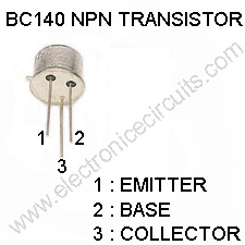
| Q1 | BC140 |
| Q2 | 2N2955 |
| LAMP1 | 12V Light |
When the potentiometer is at the up position, the capacitor will charge quickly through both 1k resistors and the diode, producing a short positive interval and long negative interval which dims the lamp to near darkness.

When the potentiometer is at the lower position, the capacitor will charge through both 1k resistors and the 50k potentiometer and discharge through the lower 1k resistor, producing a long positive interval and short negative interval which brightens the lamp to near full intensity.
The duty cycle of the 200Hz square wave can be varied from approximately 5% to 95%.
This DC Light Dimmer circuit drive more power light using 2 or more parallel 2n2955 transistors with good heat sink.
 |  |  |
Please send your ideas, which are very important for our success…
on the circuit, where does port 5 goes from the 555 ??
is it possible to have a digital potentiometer instead of VR1?
I’m designing a dimmer switch which can be controlled wireless. So I have a decoder. So basically what I want is to connect the decoder, timer and the digital pot to the dimmer switch..
pin 5 of 555 ic should not be connected any where
abou pot 5………
any body tell me.[img]http://img2.orkut.com/images/milieu/1/1255866533791/475975442/ln/Z1dvx8rv.jpg?ver=1255866534[/img]
So I can drive lamp bulb 12v for 555??
12V 2W Lamp is ok for me. I have schematic 555 for 1 led. But I want have 1 lamp bulb instead!
S1 On lamp S2 Off Lamp. I Want have 555 on 12v.
Resistor is 100K for 12V??
http://tronixstuff.files.wordpress.com/2011/01/555bistablesch.jpg
hi ……………………….
I have a string of 12v LEDs will this circuit cause any flickering?
i want design disco light circuit for “HAPPY WEDDING”. so. how can i it to design ??
Hello,
I suggest this idea :
Sunset/sunrise light dimmer 12v and 120v
– Imitate a sunrise and a sunset for a 20 minutes with light bulb.
– Between them, the light can go off, if sunlight is strong enough outside a range.
– for 12v and, if possible, 120v.
Thanks.
i want full details quk.
Hi. Can you please explainmore about the function of both transistor in the circuit ?
how can i improve this to remote controlled dc dimmer?
So,useful circuit for me. Thank you.
But i want 6Amp instead of 2Amp, can i get 12v dimmer circuit for 6Amp.