
Transmitter RF Output LED Indicator Circuit Diagram
This RF output detector circuit using a visual indicator can be useful for an RF indicator.

| PARTS LIST | |
| R1 | 560Ω |
| C1 | 330pF |
| C2 | 0.1µF |
| D1 | 1N34 or 1N60 or ECG-109 or NET-109 |
| D2 | LED |
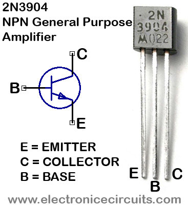
| Q1 | 2N3904 |
This circuit was used for a transmitter ON indicator.
Transmitter output or other RF output is connected to the RF input in this circuit.
 |  |
Please send your ideas, which are very important for our success…
thanks for sharing…..
what is tha connector in this cct..
Thanks for sharing
So I want to make a sensor that glows when in range of the transmitter… And to anyone including me this sounds easy…till I want it to be no larger that a 50 cent piece; although it needs to only work within 50 yards or so.
Please help, I want it for my friends Christmas present.
Lastly can you please explain what of the two “rf inputs” as suppose to go to.
Thank you for this post!