
5 WAY AC FLASHER
We use these types of circuits in most ceremonies (wesak festival, christmas, wedding, …). This 5 WAY AC FLASHER circuit running system base on cd4017 ic, timer base on ne555, output base on the component called “Triac” and power supply base on the capacitor. we don’t use steps down transformer and can be given directly 230V to this circuit .

| PARTS LIST | |
| R1 | 820Ω |
| R2 | 1.8KΩ |
| R3 | 100KΩ |
| R4 | 10KΩ |
| R5 | 10KΩ |
| R6 | 10KΩ |
| R7 | 10KΩ |
| R8 | 10KΩ |
| R9 | 330Ω |
| R10 | 330Ω |
| R11 | 330Ω |
| R12 | 330Ω |
| R13 | 330Ω |
| R14 | 1KΩ |
| R15 | 1KΩ |
| R16 | 1KΩ |
| R17 | 1KΩ |
| R18 | 1KΩ |
| R19 | 1MΩ o.5W |
| VR1 | 100KΩ |
| C1 | 0.68µF 400V mylar capacitor |
| C2 | 220µF 25V |
| C3 | 2.2µF 25V |
| D1 | 4× 1N4004 |
| D2 | 9V 0.5W ZENER |
| Q1 | 2SC828 |
| Q2 | 2SC828 |
| Q3 | 2SC828 |
| Q4 | 2SC828 |
| Q5 | 2SC828 |
| Q6 | 2SD313 |
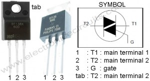
| T1 | BT138 |
| T2 | BT138 |
| T3 | BT138 |
| T4 | BT138 |
| T5 | BT138 |
| IC1 | NE 555 |
| IC2 | MN 4017 |
BT138 PIN CONFIGURATION
5 WAY AC FLASHER NOTE:
Use heat sink when more lights are switched on by the triac.
Mica sheets use between Triac and heat sink when using a single heat sink
use mylar type 0.68µF 400V capacitor to the power supply (C1) .
Don’t touch any component, when circuit is connected to the 230V AC power.
Please send your ideas, those are very important for our success…
 |  |
Keep posting stuff like this i really like it.
Hi there is some mistake in the diagram around triac and driver transistor. in the present configuration triac is superfluous, as the entire current is flowing through the transistor. Kindly check the diagram and correct.
Dear Seetharaman,
this 5 WAY AC FLASHER CIRCUIT is correct. i designed and tested it. it hasn’t any problems. If you interchange LEDs common line to other AC line, it happened. thanks for your idea.
this circuit completed propaly. but system is not working.
Hi ..!
@ All
I tried this circuit with the R14 to R18 – 1k 1\4w
R9 to R13 330 Ohem 1/4W
It ddnt work @ all.
@ seetharaman
then I connect one A/C line to Led (-) end and then the 1K resistor blow up. One the 5W 230V bulb atcivated.
Could some one please let me know the working diagram of this circuit please..!
I am very happy that you said that post…
all cathodes of the leds should be connected to pin no 1 of ne555 ic
i parallel it 5 WAY AC FLASHER CIRCUIT DIAGRAM now im your rss reader
HI
I have been trying this circuit. And finally I was able to light up one 5w bulb. When I attach triac for rest of the positions(Out 2-5) its not working. 🙂
Can this be adapted for 100V 60Hz?
Oops. That should be 110V at 60Hz.
good work….
I want to parraral most bulb. Can do it