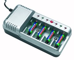
Ni-Cd Battery Charger Circuit
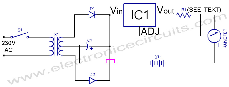
This Ni-Cd battery charger is a circuit based on the regulator IC lm317.This circuit is very simple and uses minimum components. By varying value of resistor R1 from 1 ohm to 120 ohms, charging current can be varied from 10 mA to 1.25 A. This circuit functions as a constant current generator.

| PARTS LIST | |
| R1 | from 1 ohm to 120 ohms (see text) |
| D1 | 1N4002 |
| D2 | 1N4002 |
| C1 | 1000µF 40V |
| IC1 | LM317 |
| Ammeter | 250mA Ammeter |
| BT1 | 4×Ni-Cd cell under charge |
| X1 | 12V-0-12V (250 mA) SEC |
| S1 | ON/OFF Switch |
To see LM 317 pin configuration
Construction is fairly simple and it can be constructed on a veroboard or tag board. As a general rulle all Ni-Cd batteries should be charged at the maximum charging current of 1/10 ampere-hour rating of the battery. This should never be exceeded. Exact charging current can be set by using a potentiometer or a preset in place of R1 and putting an ammeter or multimeter in series with the load. As the maximum input voltage to IC is 40V, input voltage should always remain less. Proposed circuit is suitable for charging four cells in series. But the maxmum number that can be charged will depend on input DC voltage o regulator.
This circuit is vary rugged and reliable. Output current is virtually independent of load and can be controlled very precisely. Almost any type of Ni-Cd battery can be charged. IC should be fitted with heatsink (LM317T is plastic package of LM317K with same rating but costs only half as much). Typical specifications for a Ni-Cd cell are as follow:
- Nominal 1.2V Full charge 1.4V.
- Charging time max. 12 hrs.
- Discharge rate on storage is 0.014V/24 hrs.
- Totally discharged cell recovers fully on 12hrs charging
- Electrolyte seepage does not affect performance.Wipe cell with dry cloth.
Please send your ideas, those are very important for our success…
how converted the 1.2v single battery circuit digrams