
12V Battery Charge Nominal Discharge (Low) Indicator Circuit
This battery level indicator circuit monitors car battery voltage. It provides an indication of nominal supply voltage as well as low or high voltage.

| PARTS LIST | |
| R1 | 1.5kΩ |
| R2 | 1.5kΩ |
| R3 | 1kΩ |
| R4 | 1.5kΩ |
| R5 | 1.5kΩ |
| R6 | 10kΩ |
| R7 | 10kΩ |
| VR1 | 10kΩ Preset |
| VR2 | 10kΩ Preset |
| D1 | Green LED |
| D2 | Yellow LED |
| D3 | Red LED |
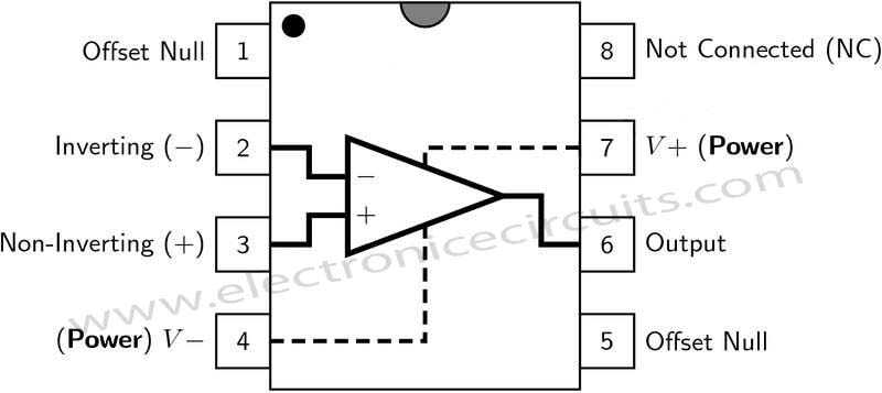
| IC1 | LM741 |
| IC2 | LM741 |
VR1 and VR2 adjust the point at which the red, yellow and green LEDs are on or off. For example the red LED comes on at below 10V, and the green LED at above 12V. The yellow LED is on between these values.
Battery level indicator circuit adjustment:
Turn both presets to ground side (anticlockwise) . Then Gives 10v to this circuit using adjustable power supply and adjust VR2 to yellow led comes on. Again gives 12v to circuit and adjust VR1 to green led comes on.
 |  |  |  |
Please send your ideas, which are very important for our success…
nice site thanks for the link, nice monitor 🙂 great design, well not bad service will take a look closer, well not bad site, not so many programs listed but looks quite great.
The remarkable project at you, it is interesting you create a resource? If yes, at me on a site can find a lot of useful to creation of different projects. Thanks for cooperation.
Отличная статья! большое спасибо автору за интересный материал. Удачи в развитии!!!
Sorry for my bad english. Thank you so much for your good post. Your post helped me in my college assignment, If you can provide me more details please email me.
Keep posting stuff like this i really like it
Хороший у вас блог! удачи в развитии
Entirely kindly blog, author a wonderful gentleman’s gentleman! Desing is cool!
It worthfull project keep it up
It is OK but there is one problem. It only show the actual Battery voltage level when battery is disconnected from Charger. When it is conected to charge then the charger voltage (like 14v) appear on circuit terminal so it will show that voltage.
I need a circuit will show the charge status during charging(i.e the chrger connected to battery).
Please anyone can helf me?
What is value of vr1andvr2. And their function
Over 15.5 volts is degraded battery supravoltata green lights but will be red, but how? Thank you!
How modify, green and red indicate as above 15.5 volts battery voltage is considered too high
How did you come up with those values of R1 up to R5?