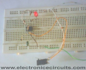
Power Supply Failure Indicator Circuit
Many circuits, especially digital systems such as random access memories and digital clocks, must have a continuous power supply to ensure correct operation. If the supply to a RAM is interrupted then the stored information is lost, as is the time in the case of a digital clock. so we can you this power failure indicator circuit.
The supply failure indicator described here will sense the interruption of the power supply and will light a LED when the supply is restored, thus informing the microprocessor user that the information stored in RAM is garbage and must be re-entered, and telling the digital clock owner that his clock must be reset to the correct time.

| PARTS LIST | |
| R1 | 100kΩ |
| R2 | 10kΩ |
| R3 | 10kΩ |
| R4 | 680Ω |
| C1 | 10nF (103) |
| D1 | LED |
| D2 | 1N4148 |
| IC1 | 741 |
| PB1 | Push Button Switch |
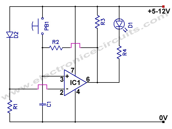
When the supply is initially switched on the inverting input of IC1 is held at 0.6V below positive supply by D2. Pressing the reset button takes the non-inverting input of IC1 to positive supply potential, so the output of IC1 swings high, holding the non-inverting input high even when the reset button is released. LED D1 is therefore not lit.
When the supply is interrupted all voltages, of course, fall to zero. Upon restoration of the supply the inverting input of IC1 is immediately pulled up to its previous potential via D2. However C1 is uncharged and holds the non-inverting input low, so the output of IC1 remains low and D1 lights.
Please send your ideas, which are very important for our success…


after inttrruting the supply for how much time the led will glow.
thanks sir , this is very helpful for me .
sir, i request u that tell us brefily explanations component used in this ckt. so that we can teach much better.
thanks again my dear sir.
after inttrruting the supply for how much time the led will glow IN POWER FALIOR INDICATOR
sir please, inform me, components name used in this ckt