
Code Practice Oscillator Key Circuit
Morse Code is a two sound for representing letters of the alphabet, numerals, and punctuation marks by an arrangement of dots, dashes, and spaces. Morse code transmits electrical pulses of varying lengths or mechanical or visual signals, like flashing lights. You can practice morse code using below circuit.

| PARTS LIST | |
| R1 | 10kΩ |
| R2 | 100Ω |
| R3 | 100Ω |
| R4 | 18kΩ |
| R5 | 180kΩ |
| C1 | 0.047µF |
| C2 | 0.047µF |
| C3 | 0.0022µF |
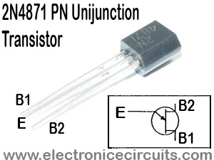
| Q1 | 2N4871 |
| Q2 | BC109 |
| SW1 | Key Switch |
| LS1 | 4Ω-8Ω speaker |
Q1, a unijunction transistor, generates a sawtooth of about 1.5kHz to 2kHz, depending on C1 and R1. Q2 acts as a speaker driver. A 9V battery is used, and the keying is done by keying the supply line.
Please send your ideas, which are very important for our success…
hi