
Colpitts 1MHz To 20 MHz Crystal Oscillator Circuit
This is a simple Colpitts crystal oscillator for 1 to 20 MHz,

| PARTS LIST | |
| R1 | 220kΩ |
| R2 | 1kΩ |
| C1 | 82pF |
| C2 | 0.001µF |
| C3 | 100pF |
| C4 | 0.01µF |
| C5 | 0.001µF |
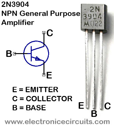
| Q1 | 2N3904 |
| XTAL1 | CRYSTAL (1 to 20 MHz) |
This can be easily made from junk-box parts (provided that a crystal is handy).
Please send your ideas, which are very important for our success…
Copied your osc. circuit. Colpitts. I intend to use it in a receiver 455 Khz BFO and hopefully make the crystal series capacitor variable to “pull” the frequency through part of the audio range. Should be more stable than the standard L-C layout.
So could I plug the 50mV output of this into an op amp and amplify it? What may be a good amplifier to do that with?
i m having some problem in producing a 1mhz oscillator, if i use the circuit that provided here, can i manage to make it?.. and, i have no idea about it, and in an absolutely troubled situation.. thank you..
This schematic is not universal for broad frequency range because it`s purpose is for the natural frequency of the crystal.It can be pulled down only with frequency dividers and also needs precise calculation for different crystals.
@almat – just substitute a parallel coil and cap for the crystal and you will have a variable frequency oscillator.
Can the frequency be doubled? I understand this is for the natural frequency. I want to use the second harmonic of 3.579MHz crystal to build a 7MHz frequency source to test my other circuit. Any ideas on how to do that?
Dlp projector bypass 5pin
Is it important to use 2N3904 transistor?
I’ve build this circuit with BC547 and looks like it works OK, but I don’t know if it could be better.
http://postimg.org/image/8f3y7n1c3
Thank you
why’d we use that value of capacitors? do you have any calculation or something?
I found it better to remove C2, and make C1=1nF, C3=10nF, and C5=100pF, all other being the same.