Skip to content
Electronic Circuits

DIY Hobby projects, diagram, schematic

Electronic Circuits

DIY Hobby projects, diagram, schematic

Over Voltage Protector

electronicecircuits, February 26, 2010August 17, 2023
Over Voltage Protector

Over Voltage Protector Circuit Using SCR
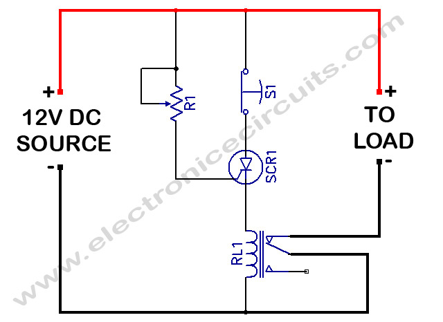
Over Voltage Protector Circuit


PARTS LIST
VR12.5kΩ
SCR11A 50V SCR
S1N.O. Switch
RL112V Relay

A silicon-controlled rectifier is installed in parallel with 12v line and connected to a normally-closed 12v relay, RL1. The SCR’s gate circuit is used to sample the applied voltage. As long as the applied voltage stays below a given value, SCR1 remains off and RL1’s contacts remain closed, thereby supplying power to the load. When the source voltage rises above 12V, sufficient current is applied to the gate of SCR1 to trigger it into conduction. The trigger point of SCR1 is dependent on the setting of R1. Once SCR1 is triggered (activating the relay), RL1’s contacts open, halting current flow to the load.

Please send your ideas, which are very important for our success…

Electronic Circuits Electronic Switch

Post navigation

Previous post
Next post

Comment

  1. ya.vasch1950 says:
    May 9, 2013 at 9:51 pm

    Хорошо бы было если б схема отключала при14,7В ивкючалась
    при 13,5В.
    Іван.

    Reply

Leave a Reply Cancel reply

Your email address will not be published. Required fields are marked *

  • Diagrams
  • Privacy Policy
  • Software
  • Contact

Recent Posts

  • LM317 CONSTANT CURRENT CALCULATOR
  • 5V buck converter – LM2576 simple DIY project
  • ICL7107 PANEL METER
  • Precision 1Hz clock generator circuit
  • Toggle to Momentary Switch Using 555 Monostable

Categories

  • Circuit Tutorials
  • Electronic Circuits
  • Electronic Software

AC Projects Alarm Circuits Amplifier Circuits Amplifiers Antenna Circuits Battery Charger Calculator software Circuit Designer Control Circuits Converter circuits Crossover Circuits Data Sheets Digital Circuits Electronic Switch Flasher Circuits Game Circuits IC Programmer IC Programming Indicator Circuits LED Circuits Light Circuits Logic Circuits Measuring Circuits Meter Circuits Microchip Motor Circuits Music Circuits Oscillator Circuits PCB Designer PIC Power Amplifier Power Guard Power Supply PreAmplifier Circuits Radio Circuits Regulator Circuits Regulator Diagrams Regulator Schematics RF Schematics Sensor Circuits Tester Circuits Timer Circuits Transmitter Circuits Tutorials Vacuum Tube

©2025 Electronic Circuits | WordPress Theme by SuperbThemes