Toy DC Motor Control Circuit With SPEED, INERTIA, BRAKE, CRUISING Controller
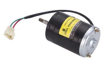
ere is a versatile project to control the speed of a small electric motor and also to bring it to a dead stop instantaneously. Provision is also made to let it cruise along at a slow speed if so desired.

| PARTS LIST | |
| R1 | 150kΩ |
| R2 | 1kΩ |
| R3 | 1kΩ |
| R4 | 470Ω |
| R5 | 56kΩ |
| R6 | 680kΩ |
| R7 | 1kΩ |
| VR1 | 500Ω |
| VR2 | 25kΩ |
| VR3 | 50kΩ |
| VR4 | 25kΩ |
| C1 | 470µF 50V |
| C2 | 1µF 50V |
| C3 | 1µF 50V |
| C4 | 1µF 50V |
| C5 | 1µF 50V |
| C6 | 470µF 50V |
| D1 | 1N4001 |
| D2 | 1N914 |
| D3 | 1N914 |
| Q1 | 2N3055 |
| Q2 | 2N3055 |
| IC1 | NE556 |
| IC2 | LM741 |
| IC3 | 7815 Regulator |
| S1 | Switch |
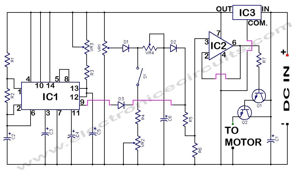
The circuit is built around two of the most popular ICs : 556 and 741. IC556 is a dual timer whereas IC741 is an Operational Amplifier.
The voltage to start the motor is provided by the charge on C6. The rate at which this capacitor gets charged is determined by the INERTIA control VR4. So, to start the motor, decrease the resistance of the speed control VR1. The Motor will accelerate at a rate determined by the inertia control. If the speed control is suddenly increased to its maximum value, the motor speed will keep decreasing till it comes to rest after a minute or so. To bring the motor to rest quickly, the speed control resistance is set at maximum, and then use the BRAKE control. As the brake control is adjusted the rate of deceleration will depend upon the inertia control.
The slow cruising speed of the motor can be adjusted by varying the CRUISING speed control.
thus, the gadget has the following controls : SPEED (VR1), INERTIA (VR4), BRAKE (VR2) and CRUISING mode (VR3).
How it works?
The voltage on C8 is determined by VR1 via D1 and VR4. The voltage decreases slowly via R5 and R6 when the speed control is brought to its minimum position, but this voltage will decrease quickly via VR4 and VR2.
The switch S1 is provided to bring the brake control in circuit. When the motor is running at full speed, keep S1 open.

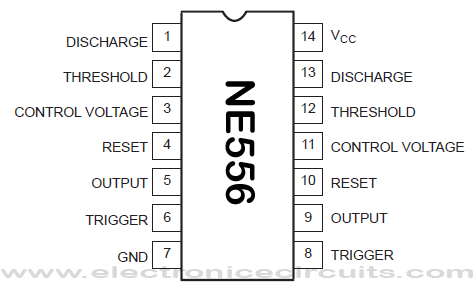
The dual timer 556 (IC1) functions in two modes. In the first mode it functions as a bistable oscillator producing 100Hz negative pulses at pin 5. In the second mode it functions as a monostable oscillator which is triggered by voltage pulses at pin 8. Pin 5 is connected to pin 8. Therefore the output of the timer consist of positive pulses and are available at pin 9. The width of these pulses is controlled by VR3.
Diodes D2 and D3 form an OR GATE which allows either the voltage on C6 or the positive pulse voltages of the timer (pin 9), to IC2, depending on which of two types of voltages happens to be higher in magnitude.
IC2 is the operational amplifier 741. It functions as a unity-gain voltage follower. The output of this IC is applied to the Darlington-Pair amplifier Q1 and Q2. This amplifier provides current about 800mA to operate the motor.
Setting up is very simple. Connect a suitable voltmeter to the output (pin6) of IC2. The meter should read about 1.5V. Slowly increase the speed control and the voltage on pin 6 should rise gradually to a maximum of about 12 volts. Next, set the speed control to minimum : the output of IC2 should remain at 12 volts for a minute or so. Now operate the brake control fully; the voltage on pin 6 should decrease to about 1 volt.
To check the operation of the slow cruising speed control, shut the speed control, and apply full brakes to ensure that C6 is fully discharged. Now, operate VR3 slowly. The Voltage at pin 6 of IC2 should rise from about 1 volt to 5 volts.
Ensure that Q1 and Q2 are mounted on proper heat sinks, since these are power transistors.
Note: If the voltage settings indicated above are not easily discernible, change the values of C2 and C5 to 100 microfarad temporarily. After setting up, replace the original capacitors as shown in figure.
This project can be utilized to operate an electric motor-driven toy train as well. Connect the output of Q1 and Q2 one rail and the negative terminal to the other rail. The motor connection, then, should also be made correctly to the rails.
The power supply is designed to separate the Control Supply from the traction supply by means of IC3.
Please send your ideas, which are very important for our success…
Very nice information.
I LOVE THIS BLOG!!!
i want you to send circuit diagram of motor speed controlar
aren’t 12-2, 13-1 pins the same? why are you connecting R2?
Dear Sir i am interested to work on dC motor control circuits please furnish me some sample circuits
thank you
M K BASHA
Dear Sir please send me DC Motor control Circuit for 2 Wheeler Vehicles
Thank you
M K BASHA
whats the max voltage can be use for the supply? Can i use 24v dc motor with 24v battery?
most helpful to my pupils……
I will be grateful, if you could provide me a schematic diagram of 3 Volt DC Motor Control operated by 2x 1.5 Volt Cells
Hi sir
Iam a power engineering and I need ideas of senior projects and some control circuit for dc motor
Thanks
Thank you Sir.